
Process Safety Management (PSM) that covers industrial facilities are required to manage risk and regulatory compliance for pressure-relief systems (PRSs) and pressure-relieving devices (PRDs).
PRDs are an important line of defence in your facility and a key barrier preventing overpressure events from developing into catastrophic failures. Errors in the design, installation, or maintenance of a PRS, whether sizing, rationale, installation or others, often result in loss of containment, human injury, equipment damage and catastrophic process safety events.
In this article, Clint Botard, Program Manager of the Asset Integrity Management Services business at ABS Consulting, highlights ten essential steps to optimise pressure relief system efficiency while maintaining regulatory compliance.
These steps can be divided into 3 phases: Data Validation, Scenario ID & Analysis, and Inspection and Testing.
Data Validation
The initial equipment validation phase contains the first three key steps.
The collective goal of these steps is to evaluate the system boundaries and equipment, also comparing its current performance to its intended performance.
Step 1: Develop a Master Asset List
A master asset list details all relief devices and relief systems covered by the Mechanical Integrity (MI) program. MI is among the 14 elements in the PSM standard, OSHA 1910.119. The requirements of the MI program include management responsibility, equipment selection and the execution of testing and maintenance strategies.
Appropriately trained and certified personnel are a vital part of the MI program and, therefore, a crucial part of this step.
Step 2: Validate the As-Built Condition
The as-built condition of each relief device listed on the master asset list is validated by performing field walk-downs in the facility to ensure that relief device information is accurate. Typical tasks performed during field walk-downs include photographing the device and ID tags and creating isometric sketches of each device or system.
Step 3: Ensure References for Each Device
All devices and systems need documented process safety information and references to Recognised and Generally Accepted Good Engineering Practices (RAGAGEPs).
Scenario ID and Analysis
This phase involves reviewing the PRD design and anticipated operating conditions. An experienced engineering team will review and document credible and non-credible overpressure scenarios to determine the device’s ability to perform as intended.
Step 4: Review Credible Overpressure Scenarios
After ensuring that all equipment has been documented and validated, the engineering team will begin reviewing the different scenarios to determine the governing scenario. Ultimately, the sizing and relief load calculations will be based on this information.
Step 5: Perform Sizing and Relief Load Calculations
Once the governing scenario has been determined, each device or system will need to be analysed based on the governing overpressure scenario. If the device is projected to have issues functioning like it should in that circumstance, the existing calculations will need to be updated based on that new information. Process stream properties will be reviewed and defined during this step.
Step 6: Determine if Additional Analysis is Required
As a final step in the design review and preparation phase, the engineering team will determine if additional analysis is required for the system. Examples of additional analysis include process stream flow rate and seeing if the pressure drop is sufficient to cause acoustic-induced vibration (AIV), flow-induced vibration (FIV), excessive loading on inlet and outlet piping during discharge, dispersion modelling, or runaway chemical reactions. Any steps necessary to remedy these additional issues should be performed during this step.
Step 7: Use Calculations to Determine Adequate Relief Device Specifications
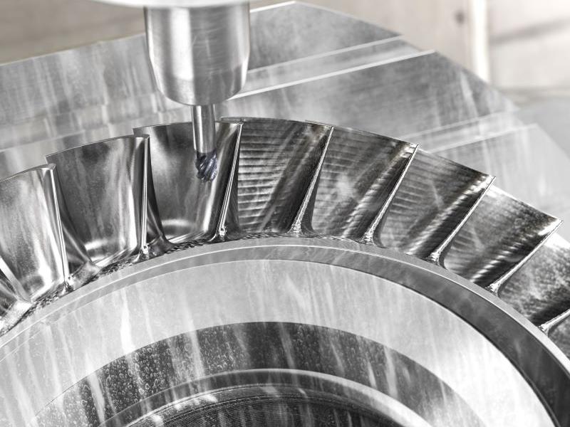
Pressure relieving devices include mechanisms such as Pressure Safety Valves (PSV) and Pressure Relief Valves (PRV). However, there are other types of pressure-relieving devices as well, such as Rupture Disk Devices and Pin-Actuated Devices.
If designed, installed and maintained correctly, these different devices will have the correct capacity for allowing anticipated pressurized fluids or gases to enter and escape so that pressure cannot build up beyond safe operating limits. Upon completion of calculations, an engineer will be able to specify and procure the correct PRV (i.e., type, code, basis, service, body, trim, manufacturer, serial no, etc.) for the requirements.
Inspection and Testing
This final phase of ensuring optimal pressure relief system efficiency involves the design and execution of an appropriate inspection and testing program while the device remains in the field (in service or out of service).
Step 8: Develop an ITP for Each Device
An inspection testing plan (ITP) helps to maintain the safety, efficiency, and effectiveness of each device. Once set, this information can be entered into the inspection database management system (IDMS) or whatever database the organization uses.
Step 9: Perform Inspection and Testing
Once an ITP has been developed for each device and entered into the data management system, inspection and testing can take place following the guidelines set forth in API RP 576.
Step 10: Evergreening
A good evergreening program will have a complimentary workflow that helps staff to identify, align, develop and execute change in a structured approach which helps a facility to protect its original investment, reduce verification burdens and not repeat expensive revalidations every 5 to 10 years.
After PRVs have been analysed, implemented and maintained in the field in “as built” status, facilities should consider implementing an evergreening workflow and strategy.
Changes that are not managed through a rigorous Management of Change (MoC) program may result in the need to review overpressure scenarios for potential impacts. Additionally, the global flare/vent/scrubber capacity may have changed resulting in inadequate pressure relief capacity.
In these cases, revalidation of PRSs or specific PRDs may be required when process safety information (PSI) is missing/inadequate or when process or organizational changes occur that impact PRS or PRD requirements.
Conclusion
Managing PRVs is complex, challenging and often misunderstood. Implementing these 10 steps will help you to optimize your PSV program and help it operate on solid ground.