Application, Balancing, Test and Torsional Issues
The design of a large electrical motor is an optimization involving various engineering disciplines. The main focus is the electrical design of the machine, which has a fundamental impact on the functionality and the performance. With increases in the power, size, and speed of the electric motors, the mechanical and torsional designs become more and more important for the operation to remain within the tightened noise, reliability and vibration limits. The latest developments and new lessons learned are described for the mechanical issues, torsional problems and coupled mechanical-electrical vibrations. Practical issues and latest developments for large electric motor and VSD systems are discussed.
The usual technology for large electric motor drivers is to use a LCI converter associated with a synchronous two(2)-pole electric motor. However, VSI (Voltage Source Inverter) technologies are becoming popular. Because of the reactive power consumption of its thyristor bridge, an LCI converter cannot properly power an induction motor. A VSI can power both induction motors and synchronous motors.
The LCI technology generates torque pulsations and a harmonic filter is usually required. LCIs have been used for decades and there have been many successful references. There is a very low harmonic content when using a VSI system (no harmonic filter required) with a better “Power Factor” (PF). A VSI solution could also offer a better cost, but references are limited. The selection between LCI and VSI depends on an application.
For large electric motors, the flexible rotor concept is used (the first critical speed usually lies below the operating speed range). The rotor should be dynamically balanced. The field balancing would not be required (whereas it is often possible). When passing the lst critical speed, the local rotational center changes from geometric to local mass center, which means, the local unbalance in an elastic rotor varies with the speed. Therefore, modal sets of unbalance weights should be used to balance each mode individually. As a minimum, “n+2” balancing planes (n=the number of modes to balance) are necessary for balancing.
A large electric motor should handle properly the thermal unbalances. Because of the inevitable use of various materials with very different thermal expansion coefficients, combined with non-uniform temperature distribution and large sizes, a symmetrical mechanical and thermally insensitive design should be achieved. A small asymmetry can cause an unacceptable dynamic load.
To reduce the risk of having non-performing drive systems shipped, full-load, full-speed performance tests of entire drive system are mandatory. Usually following tests should be conducted:
- The testing a motor alone.
- The “Back-to-back test” to verify the electric motor and the VSD performance.
- The “String test” for a complete compressor train system.
The open-circuit and short-circuit tests could be accomplished in order to determine the conventional motor losses. The no-load test, conducted at the rated speed can give the open circuit curve, which could indicate various loss contributions. The majority of the losses come from the friction and the windage. Strong cooling air flows produced by the cooling fans (an internal cooling) is associated with some losses. Typically efficiencies in range of 97-99% could be expected.
When at least two similar VSD and motor systems are being supplied, the VSD-motor back-to-back test can be done (one in the motoring mode and another in the generating mode). It is theoretically possible just to supply the losses and the reactive power demands. The bearing problems, excessive vibrations and oil systems issues are responsible for a considerable portion of failed performance tests of large electric motors. During a back-to-back test, observations are:
1) Assessment of the Motor Thermal Performance:Heat-run tests should be performed to assess the motor full-load thermal behavior at different operating and emergency modes.
2) Assessment of Motor Vibration Performance.
3) Torque Ripple Measurement.
4) Assessment of Motor Torque Overload Capability: The torque required for the startup of the train (usually a pressurized compressor), which could be 130-145% of normal torque for around 90-130 seconds.
5) Motor Voltage and Current Waveforms.
In a case study, during an electric motor test, suspicious noises and smokes were identified on the electric motor. The first observation (after the trip) given below:
- The motor shaft drop by 1.6 mm.
- The maximum temperature on the bearing reached 135oC.
- The sleeve bearings were damaged.
The root cause was the lack of lubrication oil, because of the main oil pump failure (and also the failure of standby oil pump to start).
Torsional Issues and Coupled Mechanical-Electrical Vibrations
The resonance condition of integer harmonics with relevant torsional natural frequencies within the operating speed range should be avoided. For the non-integer excitation frequencies, intersections cannot usually be eliminated.
In a typical VSD synchronous motor driven train, the disturbances are transmitted from the electric motor to the line side and vice versa. The air-gap torque is the product of the air-gap flux and the stator current (the torque pulsations usually composed of the same frequencies as the stator current). Thefundamental torsional natural frequency (1st mode) is normally of the primary importance. Based on experience, in most cases, only the first torsional mode of the train can be excited (in rare cases the second or very rarely the third). During a resonance, this first mode is capable of facilitating large amplifications of the torsional torque, which may result in a catastrophic failure of one or more train components.
High-order harmonics could not be sources of train torsional excitation. From a “Fourier” analysis, the envelope of the “Fourier” coefficient magnitudes decreases as the inverse of the frequency. Thus, the biggest magnitudes for the inter-harmonics of the air-gap torque are expected at the low-order.Nonetheless, the torsional higher harmonic order effects should be considered in simulations and torsional study reports. On the other hand, the inter-harmonics could equal the first torsional mode.
A flexible coupling using non-metallic elastic elements could present challenges such as a change in the coupling’s torsional stiffness as a result of the load variation (sometimes more than 30% change in the torsional stiffness), degradation, and nonlinear effects. This type of coupling requires an extensive sensitivity analysis to assess the torsional stiffness variation effects on natural frequencies, resonances, and dynamic stresses. These variations could easily result in unexpected resonances, unpredicted dynamic behaviors, and fatigue cases. High-torsional-stiffness and metallic-flexible couplings have generally shown a more stable operation. Yet, even for these types of couplings, the coupling torsional-stiffness variations, in the range of 10–15%, have been reported. A torsional study should be completed based on the minimum coupling stiffness (plus a sensitivity analysis).
Even for metallic high-torsional-stiffness couplings (such as the “multiple diaphragm type” or the “multiple disc type”), a 5–8% variation (usually an increase) in the torsional natural frequencies could be expected as a result of a coupling stiffness variation. For the higher-order harmonics, the variations (natural frequency variations as a result of coupling stiffness changes) are usually lower. In various case studies, above the 4th harmonic, variations of less than 2% have typically been calculated as a result of the coupling stiffness change because the high-order harmonics are not sensitive to coupling stiffness; rather they are mainly functions of the distributed system stiffness characteristics.
BIO
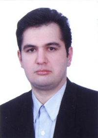
Amin Almasi is a lead rotating equipment engineer in Australia. He is chartered professional engineer of Engineers Australia (MIEAust CPEng – Mechanical) and IMechE (CEng MIMechE) in addition to a M.Sc. and B.Sc. in mechanical engineering and RPEQ (Registered Professional Engineer in Queensland). He specializes in rotating machines including centrifugal, screw and reciprocating compressors, gas turbines, steam turbines, engines, pumps, condition monitoring and reliability. Almasi is an active member of Engineers Australia, IMechE, ASME, and SPE. He has authored more than 100 papers and articles dealing with rotating equipment, condition monitoring, and reliability.
Email: amin.almasi@ymail.com


