To implement a proactive maintenance programme it’s important to know not only which equipment needs repairing, but also to understand the root cause of impending failures. Using test tools to regularly measure key indicators on critical equipment helps technicians uncover these.
The following test tools can be used to make measurements, track equipment condition over time, and diagnose failure conditions:
• Digital multimeters (DMMs).
• Clamp meters.
• Infrared thermometers.
• Insulation resistance testers.
• Thermal imagers.
• Vibration testers.
Proactive maintenance programmes vary from highly sophisticated, with continuous online monitoring and automated alerts, to more traditional offline programs that rely on inspection routes and manual measurements. Monitoring tools also vary in complexity, from digital spot infrared thermometers to thermal imagers, vibration analysers and power quality tools, to permanently mounted and networked sensors. Investigative tools vary from hand-held digital multimeters, clamp meters and insulation resistance testers to specialised motor circuit testers. Many facilities mix and match their approach, depending on equipment and scale of operations. What’s different is that these technicians repurpose tools, which are traditionally used for troubleshooting for proactive maintenance measurement programs.
Measurement guidelines
Proactive maintenance measurements aren’t that different from troubleshooting tests. Technicians are looking for signs of potential failures, so they take measurements related to failure modes. For each type of equipment they need to:
• Identify the potential failures and related key indicators.
• Determine what measurements can reduce the likelihood of problems.
• Determine how often equipment needs to be measured.
• Collect and track the results, watch for trends and initiate repairs as needed.
• Integrate all maintenance technologies into one computerised data tracking system so they share the same equipment lists, histories, reports and work orders.
Once the data is correlated the operating condition of all assets can be analysed and reported on in an integrated format.
Insulation resistance to ground
Caution: before testing cabling and motors, disconnect any electronic controls as misapplication of high voltage test equipment can destroy them. Regularly conducting the following insulation resistance tests on loads and connections can help detect imminent equipment failure:
• Ground testing line and load circuits at the starter will identify the resistance to ground of the starter, line circuits to the disconnect and load lines to the motor and starter windings.
• General thresholds: AC devices can safely operate at not less than two megohms to ground and DC devices can safely operate at not less than one megohm to ground.
• When measuring the resistance of a three-phase motor between the load legs of the starter, technicians should see high resistance and roughly equivalent measurements between phases.
Note: Insulation resistance to ground tests conducted with an insulation resistance tester require disconnecting the components or cabling to be tested from the power system. Remember to incorporate this requirement into planned downtime.
Temperature
Infrared thermometers are a low-cost monitoring option for quick, frequent measurements of specific components while equipment is operating. Identify key hot spots to track, compare those temperature readings to operational limits and watch for upward trends. For example: scan the bearing housings on motors, the switches in circuit breaker panels and the wiring connections at all equipment. For the best measurements, get as close as is safely possible to the target, make sure the surface being measured is not reflective and compensate for emissivity.
Thermal imaging
Thermal imaging tools play a key role as screening tools in a proactive maintenance program. Technicians can use them to quickly measure and compare heat signatures for each piece of equipment on an inspection route without disrupting operations. With a thermal imager technicians can quickly survey a much larger area than an infrared thermometer and see how the temperatures of different areas relate to each other.
If the temperature or thermal pattern is markedly different from previous readings, technicians can use other maintenance technologies including vibration analysis, motor circuit analysis, airborne ultrasound and lubricant analysis, to assess the severity of the problem and the time needed to repair it.
Thermal imaging applications:
• Monitor and measure bearing temperatures and condition in large motors or other rotating equipment.
• Identify “hot spots” or “cold spots” in electronic equipment.
•Identify leaks and determine fluid levels in sealed vessels and tanks.
• Find faulty insulation in process pipes or other insulated processes.
•Find faulty connections in high power electrical circuits.
• Locate overloaded circuit breakers in a power panel.
• Identify fuses that are at or near their current rating capacity or that are improperly installed.
• Identify problems in electrical switch gear.
• Capture process temperature readings.
• Perform other equipment-specific troubleshooting and diagnostics.
Vibration testing
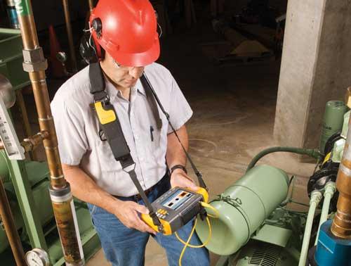
Most industrial equipment is designed to operate smoothly and with minimum vibration, so when vibration is present it’s often an indication of problems with or deterioration in the condition of the equipment. As conditions within machinery change, the amount of vibration often changes. If the underlying causes of excessive vibration are not corrected the unwanted vibration alone can often cause additional damage. Vibration data is typically collected using an electronic data collection device and an accelerometer. Measurements are taken by placing the accelerometer near each bearing location along the drivetrain, using the most appropriate attachment method. For example, a magnetic mount or a mounting pad.
Quick tips:
• Locate the sensor as close as possible to the bearing, or on a solid structural member leading to the bearing.
• Sensor position should be parallel or perpendicular to the floor whenever possible,
• Avoid mounting the sensor on thin surface areas (such as fan shrouds) and cooling fins.
• Attach the sensor to a clean, flat, bare metal surface if at all possible. Thick layers of paint, grease, oil or other matter will reduce both the holding force of the magnet and the high frequency response of the sensor.
• If possible take measurements on both ends of the motor.
• For consistent data over time it is important to place the accelerometer at the exact same location on a machine each time.
• Do not take bearing measurements from a foundation or fabricated base.
• Do not mistake seal locations for bearing measurement locations on pumps.
The vibration from a drive train may change depending on the load and the temperature of the motor. The one exception to this rule is machines which have misaligned drive shafts. It is recommended to take vibration measurements when the machine is running in a steady state and at normal operating temperature. Machines tested while still cold may have significantly different vibration signatures than those at normal operating temperature, because temperature affects shaft alignment and operating clearances due to thermal expansion. In the case of pumps, cavitation, air ingestion or discharge pressure will affect vibration readings and pumps should not be tested with the discharge valves closed. However, if they must be tested in a recirculating condition, the recirculating valve may be partially closed to achieve a normal discharge pressure. When the data has been collected, it must be analysed to determine the source, location and severity of the faults. Used regularly as part of a proactive maintenance programme, vibration test equipment can often identify potential mechanical problems weeks, if not months, prior to a catastrophic failure.
Resistance
Caution: resistance measurements must be made with the circuit power off. Otherwise, the meter or circuit could be damaged. A digital multimeter can check the resistance across most connections. High resistance readings can signal degraded connections, which can cause reduced supply voltage, nuisance tripping and potential equipment failure.
DMM Notes: most DMMs measure down to 0.1 ohm and some measure as high as 300 megohm. For accurate low resistance measurements, use the DMM’s REL function to eliminate test lead resistance.
DC and AC current
Caution: after measuring current with a DMM don’t forget to move test leads back to their voltage-measuring connections before attempting a voltage measurement. Loads may draw a slightly higher current as they age. Regularly measuring current can help technicians track the reliability of equipment. Use either a clamp meter or a DMM combined with a current clamp to measure current.
Voltage balance
A greater than two percent voltage imbalance can reduce equipment performance and cause premature failure. Use a DMM to check voltage between phases for voltage drops at the protection and switchgear delivering power from the utility and at high priority equipment. Voltage imbalance can be calculated with the following formulas:
• Average volts = (ph1 volts + ph2 volts + ph3 volts)/3,
• Percent voltage imbalance on ph1= ((ph1 average voltage)/average volts) x 100.
Note: voltage drops across the fuses and switches can also show up as imbalance at the motor and excess heat at the root trouble spot. Always double check with a thermometer.
Current balance
Another root cause for equipment overheating is current imbalance. Use a clamp meter or an AC current clamp with a DMM to check the current draw on each of the three legs. To determine average current, sum the current from all three phases and divide by three. Then, calculate the percentage imbalance by subtracting the actual on one leg from the average amps, then divide by the average amps and multiply by 100. More than 10 percent current imbalance can be a problem.
Inrush current
If a motor isn’t performing correctly or if a circuit is tripping unexpectedly, check inrush current at start-up with a clamp meter or a DMM designed to capture inrush current. Inrush current can reach up to twelve times the normal operating current, much higher than the circuit breaker rating, without tripping the breaker, as long as the circuit isn’t overloaded. Evaluating inrush current depends on comparisons of inrush measurements over time for that motor.
To find out more go to Fluke www.fluke.com.au or email mirna.maroun@fluke.com