Kevin Kevany gives three perspectives on power factor correction: a lesson, a beer and a promise.
When it comes to the subject of power factor correction, all fingers point to Mark Empson, author (of, amongst others, of the “No BS Guide to minimising EMC with VFDs”), blogger, creator and administrator of what seems to be half-a-dozen highly-technical websites. In addition, Empson is an electrical/electronics engineer, a director of Advanced Motor Control Ltd, in Christchurch, the owner of L M Photonics Ltd, a radio ham and a genealogist too. He reckons his specific skill is as a “motor control solutions provider and problem solver in industrial installations involving motion control”.
“I have a strong belief in empowering people to work with the technologies and solutions, so I frequently run training seminars at Advanced Motor Control, where I’ve been for just over a decade, on a wide range of topics, including causes, effects and solutions. As a company, we believe the end result is most important. We have a good technical team and work with clients to establish what their real needs are and help to find a working solution.
“We have expertise in the fields of motor control using VFDs, also known as VSD or variable speed drives in New Zealand, soft starters and automation; plus a high skill level in the technologies that both cause EMC and harmonic issues and the technologies which can be used to provide working solutions,” he adds.
Why bother about power factor correction (PFC), you might ask, since it seems to be something easily shrugged off, albeit with a somewhat anxious look over the shoulder of the “shrugger”?
Perhaps that should read: “What do you get without PFC?” How about:
•Increased energy costs (increased kVA charges).
• Higher transmission and distribution losses.
• Variable voltage regulation.
• Constrained supply capacity.
Power factor – the basic principles
Having got your attention – I trust – it’s time to lay in a bit of ground work with the ‘No BS expert’. “Let’s start with power factor. It is the ratio of the Kilowatt (kW) – the real power in the load in thousands of watts – to the kVA, or apparent power in the load, and is a measure of how efficiently the current is being used. If the power factor is less than 1.0, the current is not being used to maximum efficiency. There are two types or sources of reduced power factor: displacement power factor and distortion power factor.
“Displacement power factor is caused by a reactive component in the load. If there is an inductive component in the load, then there will be an inductive current flowing in addition to the resistive current. The inductive current follows the voltage waveform by 90 degrees.
“Likewise a capacitive component causes a capacitive current which leads the voltage waveform by 90 degrees. The vector sum of the reactive (capacitive and/or inductive) current(s) and the resistive current results in a single current with a phase angle before (leading) or after (lagging) the voltage waveform.
“The displacement power factor value is the cosine of the angle between the voltage waveform and the resultant current waveform. From a practical point of view, the displacement power factor is typically decreased (made worse) by inductive loads such as induction motors, transformers and lighting ballasts,” says Empson.
Which brings us to distortion power factor, probably something a little easier to grasp based on our everyday exposure to lift music. Empson again: “To give you the technical background first; distortion power factor is caused by non sinusoidal load currents which are made up of harmonic currents. These harmonic currents are caused by solid-state rectifiers and controllers.
“Poor distortion power factor is commonly caused by VFDs (Variable Frequency Drives), DC Drives, switch mode power supplies, computers and most electronic products. This causes reduced non-productive load on the system and reduced supply current.”
According to Empson, power factor comes in two ‘flavours’, displacement and distortion. “Displacement power factor is caused by inductive loads, such as induction motors and can be corrected by adding power factor correction capacitors. On the other hand, distortion power factor is caused by non-linear loads, such as switchmode power supplies and VFDs, which cause harmonic currents. Distortion power factor can only be corrected by the use of either active or passive filters. Since there are no domestic penalties in New Zealand for having a poor power factor, there is no advantage in adding power factor correction in the average domestic installation,” Empson says.
But it remains a constant problem for IT organisations, according to Emerson’s Arunangshu Chattopadhyay, Head CTS – Power Product Manager, Emerson Network Power Asia. “IT organisations continue to be faced with slimmer budgets and electrical consumption issues. As infrastructures change and demands grow, energy-efficiency has become a popular point of focus among IT infrastructure components.
“This trend explains why power factor has emerged in the industry as an important key to enabling the most efficient use of electrical power. Power factor is often a dimensionless number between 0 and 1 when assessing the ratio of the real power flowing to the load over the apparent power in the circuit,” says Chattopadhyay.
“Power factor is an important measure of power quality and shows how energy is efficiently drawn from an AC source. A higher power factor means reduced power (kVA) consumption which results in reduced electrical cabling, switchgear cost, and it is often associated with reduced harmonic level which improves the efficiency of an electrical system by reducing transmission system losses too.
“Various analogies have been used to describe power factor. I particularly like the one used in an article in the Australian quarterly, Industrial Electrix Magazine, which further simplifies the concept of power factor, likening it to a glass of beer!”
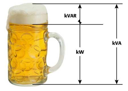
Beer tankard visual
“Let’s say a large, cold beer is ordered to quench the thirst of a thirsty individual. The beer has some froth on top which does nothing to quench the individual’s thirst. This represents the kVAr (reactive power). The beer does quench the thirst – this represents the kW (real power). The total contents of the mug (the beer and the froth) represent the kVA, or apparent power. The glass needs to be full of beer – with no froth – so the thirsty person drinking it, gains maximum benefit from the full glass of beer. That means it is the same for maximum efficiency with power, as the system should not be drawing any kVAr (or froth) in the analogy,” Chattopadhyay says.
According to him, Emerson Network, “as the world’s leading enabler of BCC (business-critical continuity), delivers innovative solutions which run efficiently, while maintaining the necessary level of availability and reliability”. This includes the introduction of power supplies with high PFC to keep pace with today’s demanding electrical requirements.
“High power factor means companies can handle the increased load without the risk of overloading, while meeting efficiency goals. PFC prevents noise, harmonics and distortion from being passed on to connected loads or from being fed back to the utility. Currently, to coin a phrase, almost every new server and networking device requires a power factor as high as 0.98. Which brings us to the Liebert GXT3.”
Providing the same capabilities of a physically larger system, the Liebert GXT3, with 0.9 power factor, has been developed using “True Online Double Conversion” technology to help customers improve power infrastructure, while reducing overall operational costs. Emerson Network claims it is “one of the most-advanced-technology UPS systems in its class” and “leads the industry in combining small size, high capacity and high reliability features”:
• Zero transfer time from external to internal power;
• Output power factor of 0.9 better matches up with switch-mode power supplies used in today’s IT equipment;
• 4-8 minutes of battery backup time at full load;
• TVSS circuitry for additional protection from spikes, surges and other power anomalies;
• 2U rack/ tower and mini-tower models;
• User-replaceable, hot-swappable batteries;
• Two-year, no-hassle replacement warranty; and is
• Suited to large enterprise requirements as well as SMB and SOHO users.
Back in 1985, Ron Davey, the current MD, founded Mahanga Holdings Limited, initially as an agency/distribution company trading in heavy electrical products. Since then, the company has expanded to incorporate associated companies, which collectively employ ten permanent staff in New Zealand and Australia, with a manufacturing facility in Auckland. Most of the group’s detailed engineering activity is undertaken at this combined office/warehouse/factory facility of 13000-sq ft., with a branch in Sydney.
The group has grown over the years to include Mahanga Holdings Limited Auckland, the marketing arm of the group; Power Consultants Limited Auckland; Electrical Distribution Equipment Auckland and Power Consultants Pty Ltd Sydney, Australia. The principle functions of the group continue to be representation and distribution of heavy electrical equipment for power generation, transmission, distribution, supply networks, heavy-industry and large commercial developments and enterprises. It manufactures medium and high voltage electrical distribution and automation equipment for integrated networks.
Engineering design and investigative services; budgetary and quotation services; project management, contract supervision and installation, plus training make up the balance. Power Consultants is one of New Zealand’s leading specialist suppliers of PFC services and products, having installed more than 40-million VAr of power factor correction throughout Australasia.
“Because we also manufacture power factor correction gear, we are very aware of what to look for when carrying out a site survey. We won’t just send you the results of your survey with a ‘kVAr required’ column. We will comment on anything we may have seen at your site that may affect the performance or design of a suitable unit. Combining our knowledge of the industry with our years of experience ensures that this survey will produce what you want – a comprehensive study of what it will take to correct the power factor on your site,” a spokesperson says.
Power Consultants can model parts of a customer’s power system to determine the resonance conditions and harmonic paths, therefore solving harmonic interference problems before they begin – with equipment only, components only or consulting for capacitors, filters and blocks for an electrical system.