Machinery needs to be correctly installed, aligned and maintained to perform satisfactorily, otherwise it may suffer premature and accelerated wear and tear – leading to expensive down time, possible irreparable damage, lost production and operator frustration.
Machinery breakdowns account for many plant management and maintenance department headaches. Product quality, machinery accuracy and serviceable life of production machinery all suffer through misalignment. It follows that costly repairs, downtime and scrap can be reduced if due attention is given to the alignment of machinery on initial installation and periodic checks performed during planned maintenance programs.
Machinery alignment generally deals with the alignment of rotating axes and planes – eg:
• The alignment of shaft couplings where the rotational axes of the shafts are required to be collinear.
• The tool path on a lathe needs to be parallel to the headstock spindle axis.
• The rotating axes of individual rolls in a printing machine need to be parallel and square to the material flow path or longitudinal centre line of the machine.
The three main factors to consider when installing and/or aligning plant and machinery are foundations, environment, alignment technique and post alignment monitoring.
Foundations
Too often poor machinery performance is traced to the foundations. It is quite common to find heavy machines have simply been bolted to the existing factory floor and across two separate concrete pads. Inadequate or poorly designed foundations are unlikely to show up dramatic effects while machinery is installed, but will contribute significantly to loss in accuracy, product quality, service life, and operational problems as the alignment of the machine deteriorates due to uneven settlement or movement of the foundations.
The principal requirement of foundations are:
• To support the machine and prevent it from sinking through the floor.
• Reinforce the base or frame of the machine thus giving additional rigidity.
• Fix the machine’s position relative to other machines, eg. to a common centreline.
• Provide stability where the foundations are used to provide a datum or reference plane for levelling and aligning a machine.
• Isolate the machine from other machines to prevent the transmission of vibration.
Environment
Often a machine operator’s statement that his or her machine performs better on particular days or times is quite true. All machinery is affected by external influences such as sunlight, temperature, vibration and draughts. It is important to recognise the effect these external influences have on the alignment of a particular machine. Recently I carried out a three week alignment monitoring exercise on a large double column planer. The results indicated that column movement, and changes in the level and straightness of the machine bed slideways, followed a 24-hour cycle and were related to air temperature variation.
Variation in room temperature contributes significantly to machine instability due to expansion and contraction – a variation of just four degrees Celsius over a 24-hour period can make a considerable difference to the alignment of large machine tools when the tolerances are very close. Particular problems occur when localised heating takes place as small and large parts are affected at different rates.
If environmental effects are suspected of causing operating problems then it is worth considering carrying out a monitoring exercise on the machine for a period of time to isolate the causes. Comprehensive monitoring can be carried out using electronic sensors and chart recorders or data loggers to collect the information for analysis.
Alignment techniques
The following procedure should be used as a guide when considering the alignment or realignment of any machinery:
• Select the reference or datum features appropriate to the machine. Possible features might be the slideways for a lathe; nip roll for plastic film extrusion; recoiler arbor on slitting machinery; the table surface and column slideways on a horizontal borer; an offset centreline on continuous strip handling machinery; bearing centres; and shafts or couplings. If a number of machines need to be aligned as a unit or system then it is usual to choose a reference feature, as a datum, on the machine that is most difficult to shift. Then the other machinery is moved into alignment with this datum reference.
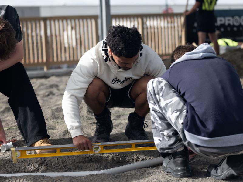
• Decide on the important parameters required for the machinery, and the parameters that need to be checked on individual components or units. Possible parameters include level, straight, flat, square, parallel, perpendicular or plumb, and so on.
• Decide on the tolerances, and be realistic. There is little point in trying to set a train of rollers parallel to each other to within 0.05mm if the rollers are of extruded aluminium and not round to within 0.1mm anyway. A machine can be set up to within 1.0mm very quickly, but it may take ten times longer to set it up to within 0.1mm and perhaps 100 times longer to set it up to 0.01mm. When setting tolerances consider the manufacturer’s recommendations, product, environment, maximum speed, adjustment method, alignment method, instruments and equipment. A reasonable alignment tolerance can be identified as the allowable deviation from a particular parameter (eg. level, or straightness) that has been proven by experience to allow a machine to perform satisfactorily without adverse effect.
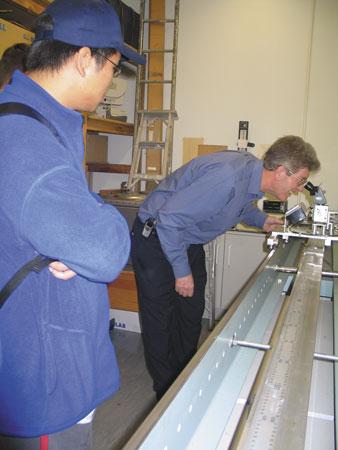
• There is a variety of instruments and equipment available to assist with alignment. Some of the more expensive equipment such as lasers, theodolites, and precise optical levels can be hired. Instruments must measure to better than the required tolerance and be checked for calibration.
• Train the alignment crew to use the instruments and equipment properly.
|
Adjusting machinery
Patience and planning are a ‘must’ when adjusting alignment. Success is proportional to the effort put into planning and preparation. Planning includes designing or choosing the method to be used, writing it up, assembling the tools and equipment, and preparing personnel:
• Keep the alignment method simple; write it up if necessary for those involved to read.
• Keep notes as you proceed with the job, a graphical plot or a sketch with the instruments readings and adjustments added can save time later when trying to identify or solve a problem.
• Protect the machine against draughts and local heating if possible.
• Check the means for adjustment. Jacking screws with a fine pitch or wedge mounts are probably the most convenient, but shim packs often have to be used due to loading or location requirements. Ensure the jacking screws are clean and free to rotate or that the shims and foot locations are clean and free from burrs, folds, or kinks.
• Making a series of small adjustments with checks in-between is usually more efficient than trying to accomplish good alignment with one or two large adjustments and this is especially true if you are not following a proven graphical plotting technique.
• Keep a check on the alignment in the transverse or cross-direction as well as the longitudinal direction. This is a check for twist (or wind).
• Try to keep even loading or torque on all the holding-down bolts and jacking screws.
• Don’t be afraid to adjust for zero alignment error because there will be errors in your measurements and the machine will change its position, but overall the alignment should end up within the tolerances sought.
• If possible, use another method as a quick check on the final results achieved.
Post alignment monitoring
The initial alignment or realignment of a machine is normally carried out when the machine is cold, with allowances being made for anticipated or calculated movement due to changes in temperature, pressure and external influences such as connecting pipes. Therefore to achieve the optimum alignment for normal operating conditions it is necessary to monitor the movement of a machine from a cold start up to normal operating conditions. This will provide information about thermal growth, dynamic movement, vibration, and whether the alignment is being influenced by other sources such as connecting pipe strains. This information can then be used to make future adjustments to further improve the hot alignment of the machine.
Longer term alignment checks carried out at six or 12-monthly intervals are useful to check on machine movement, foundation settlement, or the effects caused by local modifications.
Article by Allan Patterson of the Measurement and Calibration Centre.
Contact Allan Patterson: apatterson@themcc.co.nz
|


