Voltage pulses from a variable speed drive can couple from a motor’s stator to its rotor, causing a voltage to appear on the rotor shaft. When this rotor shaft voltage exceeds the insulating capacity of the bearing grease, voltage arcs or electrical discharge machining can occur, causing pitting and fluting of the motor bearing race, damage that can cause a motor to fail prematurely. This application note explains how to use the MDA-550 Motor Drive Analyser and a shaft voltage probe to measure motor shaft voltage discharge events.
Shaft voltage discharges
Capacitive coupling between a motor’s stator and rotor can create a voltage on a motor shaft. For this reason, bearings in electric motors can suffer from wear and tear caused not only by the rotation of the shaft but also by electric currents flowing from the motor shaft to ground through the bearings. Motors powered by sine wave ac power may have shaft/bearing-to-frame voltages of about 1 to 2 V. Motors powered by the rapidly switching waveforms of variable frequency drives (VFD) may, however, have shaft/bearing-to-frame voltages as high as 8 to 15 V. Voltages at these levels can overcome the insulating properties of bearing grease and the resulting sparks can cause pitting, fluting, fusion craters, and, eventually, premature failure of the bearings and motor.
Shaft voltage probe
Capacitive coupling between a motor’s stator and rotor can create a voltage on a motor shaft. For this reason, bearings in electric motors can suffer from wear and tear caused not only by the rotation of the shaft but also by electric currents flowing from the motor shaft to ground through the bearings. Motors powered by sine wave ac power may have shaft/bearing-to- frame voltages of about 1 to 2 V. Motors powered by the rapidly switching waveforms of variable frequency drives (VFD) may, however, have shaft/bearing-to-frame voltages as high as 8 to 15 V. Voltages at these levels can overcome the insulating properties of bearing grease and the resulting sparks can cause pitting, fluting, fusion craters, and, eventually, premature failure of the bearings and motor.
Measuring device
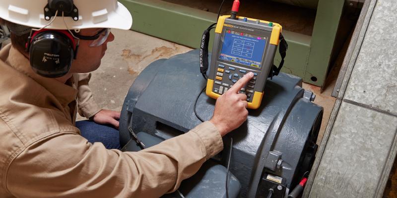
The MDA-550 is designed to quickly and easily test and troubleshoot typical problems on three-phase and single-phase inverter type motor drive systems. Next to the four-channel portable oscilloscope and recorder functionality, specific motor drive analysis functions offer step-by-step set-up guidance with on-screen information. This makes it easy to configure the analyser and get the drive measurements from the power input to the installed motor, including shaft voltage measurements.
Shaft-voltage spikes can be exceedingly fast, even below the microsecond measurement range. The Fluke MDA-550’s high 500 MHz bandwidth and fast sampling rate (up to 5 Gsample/s) make it ideal for measuring rapid changes in voltages.
Measurement results
The default motor shaft voltage measurement shows voltage waveforms as measured on the motor shaft itself. The voltage peak-peak value displayed at the top of the screen identifies the maximum level of the captured waveform, which is already an indication that high voltage levels are present on the shaft. However, the frequency with which these fast discharges occur cannot be determined this way. Utilising the “EVENTS ON” function, the MDA-550 will display waveforms with discharges based on a pre-defined minimum voltage difference and maximum time difference.
The display is updated with each waveform captured that has a steeper rise- or fall-time, along with the number of detected events per second. Discharge waveforms will show an increase in voltage to ground followed by a sharp vertical line to ground at the moment of discharge. For a detailed analysis of the last captured waveform, the MDA-550 offers the “REPLAY” feature with a buffer of the screens for the last 100 waveforms captured. The screen can be individually selected or displayed as an animation.
Voltage discharges of > 15 V and transition times faster than 50 nanoseconds can point to discharges capable of damaging bearings. However, this alone is not enough to determine potential damage to a bearing as there are many other factors influencing this.
If excessive shaft voltages are detected, it is a good practice to see if voltage discharges can be reduced by adapting the cabling, grounding, drive parameters, or lubricant. If this is not possible or does not help mitigate the problem, shaft grounding devices or an isolated shaft are useful alternatives. The effects of these shaft voltage mitigation efforts can easily be understood by comparing the number of events recorded before and after changes were implemented.
Contact Fluke ANZ at auinfo@fluke.com for more information or for an on-site demonstration.