
By Amin Almasi
Mineral oils are cost effective and widely used. Hydro-treated mineral oils are employed for their low fluid solubility (say usually one percent to four percent). Synthetic lubricants are used depending on the process, temperature and how much dilution is present. The PAO (Polyalphaolefin) oils, for example, have excellent water and oxidation resistance. The PAG (Polyalkaline Glycol) oils, which do not readily absorb hydrocarbons/fluids, are used in applications where the oil is in contact with the working fluids. One of the main disadvantages of using grease over oil is the annoying tendency of grease to cake and dry out. Usually, lubrication oil is preferred for the lubrication of a machinery.
There are four primary components to precision lubrication oil of machinery bearings and components:
- The lubrication oil selection
- The lubrication oil system
- The flow, pressure and operating conditions of lubrication oil
- The monitoring, control and condition monitoring of lubrication oil and its system
The condition-based lubrication should be part of any world-class operation and maintenance programme, and the subject of condition-based operation is gaining more and more interest in the machinery industry.
The lubrication oil condition monitoring should examine the lubricant properties, contaminants and various kinds of wear debris to determine machine health; it is comparable to a blood test on the human body. More than 65 percent of machinery failures are usually lubricant-related.
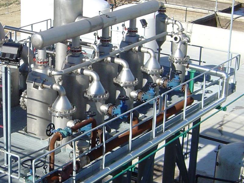
Lubrication Condition Monitoring
The oil condition monitoring could be in two major types, the “lab testing” and the “online testing”. For the first option, the “lab testing”, lubrication oil samples are sent to a laboratory, which could be an “out-of-site lab” or an “on-site lab”. The “online testing” instruments, which are meters, are installed usually in an oil circulating system in order to monitor continuously lubrication oil conditions. Particularly, “particle counters”, “moisture meters” and “dielectric instruments” should be mentioned as good examples for online monitoring. Proper lubrication condition monitoring should be selected for critical machinery.
Some data parameters have only upper limits such as particle counts or wear debris levels. A few data parameters employ lower limits like flash point and oxidation stability. Many data parameters like viscosity and additive elements use both upper and lower limits. Rate-of-change limits are effectively applied to some parameters such as particle counting, elemental wear metals, ferrous density, and others. They also can be effectively applied to monitor abnormal degradation of additives.
Special care is needed for small machines. For a small machine, the lubrication oil online monitoring is usually not feasible. The lubrication oil “lab testing” should be performed with great care. When sampling small reservoirs, such as those in small machineries below 300 kW, following the flush portion and then sampling, a complete oil change would have occurred on every small machine. Considering the increased lubricant consumption coupled with the additional cost of testing the oil samples, the overall costs would be significant.
Oil Viscosity Monitoring
The condition of lubrication oil is a critical factor in extending a machinery’s bearing/component life and overall reliability. Monitoring and managing the lubrication oil viscosity can prevent costly breakdowns because of the bearing failure. The viscosity of lubrication oil also plays a role in the energy efficiency, as demand for more efficient machinery is driving the use of lower-viscosity lubricants.
For machineries where lubrication oil comes in contact with light hydrocarbons (for example, compressors), the lubrication oil’s viscosity can break down much more quickly, increasing the risk of failure. Clearly managing lubricant viscosity is critical to maintaining machinery health. Many operators also have found that real-time temperature monitoring is inadequate to monitor lubricant viscosity. It is a common practice to monitor lubricant viscosity of many medium/large rotating machines once a month by sending a sample to a lab for testing. Rapid changes in viscosity can occur, and the results can be severe. It is recommended to install the real-time monitoring of lubrication oil viscosity (the inline viscometer) in critical machines. Monitoring the lubrication oil viscosity is the best way to prevent bearing wear and machinery failure.
Many factors can affect lubrication oil viscosity. These include oxidation, dilution, contamination, bubbles, temperature changes and others. The continuous monitoring of the lubrication oil viscosity can show traces/effects of all above-mentioned faults. An operator can look and select certain characteristics for an inline lubricant viscosity measurement system, such as menu-driven electronic controls, self-cleaning sensors, built-in temperature detection, multiple output signals, automatic viscosity control, data logging, quick change memory settings, security and alerts. A self-cleaning sensor uses the inline fluid to clean the sensor as it is taking measurements. For an automatic viscosity control, a sensor that is pre-set but reconfigurable is always preferred.
Oil Contamination Monitoring
Machinery operators are nowadays empowered to perform quick and frequent oil analysis tests particularly tests related to the oil contamination. One of the most important tests includes the assessment of the lubrication oil contaminants. There is usually a requirement for the continuous lubrication oil condition feedback from the lubrication oil contaminant monitors since the oil contamination can be occurred suddenly as result of a malfunction. Also, the oil contamination can cause machinery damages in a short time. The contaminant monitoring instruments have advanced rapidly in the past decade as their effectiveness and their importance. There are a variety of user-level contaminant monitoring instruments and methods to gain quick readings on lubricant cleanliness, dryness and other contaminant levels. An important step for a proper oil contamination monitoring program should be identifying the points (ports) for the contaminant monitoring on the lubrication oil circulating system. Two sets of points (ports) need to be identified including the primary (routine analysis) and secondary (troubleshooting) sampling ports.
One of the most important factors in the selection of lubrication oil contaminant monitoring instrument is the ease of operation/application. The “ease of use” is as important as the technical specifications (such as the precision, and other requirements). The lubrication oil contaminant monitoring instrument should be frequently used, but a moderate precision is usually sufficient.
Wear Debris Analysis
The key of a successful condition monitoring system is the early detection and swift corrective measures. One of the important aspects of the “wear debris analysis” is the weak signal capability that can be resulted in an early detection of a developing damage in a rotating machine.
The “wear debris analysis” refers to the extensive array of wear particle technologies and tactics that can help reveal the true tribological condition of a machine. These techniques should be used in combination, since individually they cannot be effective. Even an individual technique/measurement, sometimes, can be misleading. There have been many false detection reports, because people attempt to draw a premature conclusion from an incomplete/individual piece of information in the wear debris analysis.
Common important technologies used for screening purposes include the “ferrous density analysis”, the “elemental spectroscopy”, and the “particle counting and patch testing”. Complementary methods used for proper and correct monitoring/fault-detection are the “filter debris inspection”, the “magnetic plug analysis”, the “sump sediment analysis”, the “ferrography” methods, the “acid-dissolution spectroscopy”, the “particle heat treatment”, the “particle impaction testing”, the “chemical microscopy”, the “digital shape profiling”, the “rotrode filter spectroscopy”, the “gravimetric analysis”, the “ultracentrifuge” (separation of soluble metal fraction), the “pore blockage particle counting”, and many more. Again, individually, the above-mentioned methods might let a damage go unnoticed or a misleading conclusion. However, when two, three or even four trend lines move and show the same result, there can be a reliable signal that could be used for a further monitoring/investigation or even a corrective action.
The clean oil can strengthen the signal-to-noise ratio in a “wear debris analysis”. Without the background noise of dirty oil, even the weakest signals sometimes can be detected. The correct position should be selected for “sampling” points in a “wear debris analysis”. The particle/debris generating sources and the potential damage locations should be properly identified and correct sampling points should be defined. By sampling downstream of the wear generating source and upstream of filters/reservoirs, the data is not stripped by filtration or muted by dilution.
The “size” and “shape” of particles play an important role in the “wear debris analysis”. The most important indications are the particles in their original “size” and “shape” as produced from their generating sources such as bearings, gears, and other particle generation points. The circulated particles, which produced some time ago and circulated in the lubrication oil system, cannot be useful. Often, the circulated particles cannot be properly employed for the monitoring purposes because they have been “reworked” by the machine and its environment through crushing, laminating, corrosive action or others and the identification of the wear mode and the location of the particle generation are nearly impossible. Some good places to find the particles in the original “size” and “shape” are filters, sump sediment, magnetic plugs, chip collectors and similar sources.
Lubrication and Reliability
Usually, there is a risk to stop a machine for repair (or overhaul) based on only one abnormal monitoring signal. In other words, without having the benefit of multiple technologies coming to the same conclusions, the reliability of a machine cannot be properly assessed. There are usually the following three monitoring arrangements for a critical machine, the “vibration analysis”, the “oil analysis”, and the “infrared thermography”. At least one technology should be used on every major piece of equipment. If an anomaly is observed, other technologies should be applied to evaluate the machine. If at least two monitoring methods show there is an issue, a proper action should be taken. The “vibration analysis” is a commonly-used method and other two can help to confirm any detected issue.
For example, the online vibration monitoring is usually employed for the continuous monitoring of machinery’s bearings. If there is an abnormal vibration, the “oil analysis” can be used to further evaluate the bearings. If there is a slight spike in “Lead”, “Tin” or “Aluminum”, it could be concluded that there is a bearing issue. As another example, the online vibration monitoring of the bearing and the casing are employed for many gear units. If there is a high vibration recording, there could be the “oil analysis” for further reliability assessment of the gear unit. A slight increase in iron could be considered as the confirmation of a problem in the gear unit. Without having the benefit of two or even three technologies that confirm there is a reliability issue, there could be a risk to stop and open the machine and find no issue.
The fake signals of vibrations have been reported for many machines. There are numerous cases that machines have experienced a high vibration, but still healthy and can work for a relatively long time without any problem. Many machines have experienced high vibrations, even two or three times than their normal (baseline) vibration amplitudes, without any serious problem. A case study is presented here to show the importance of “oil analysis” to confirm a reliability issue. For a medium size rotating machine, the measured vibration has been tripled (three times the baseline value) during four months. During this timeframe, the oil analysis showed significant increases in bearing material and other contaminants. The machine was stopped at the first opportunity. The detailed observations showed the seal was damaged, allowing contaminants to invade the bearing which caused both high vibration (as result of bearing damages) and the oil analysis abnormalities.
Contact: amin.almasi@ymail.com